Extracting Three-Phase Boundary Graphs
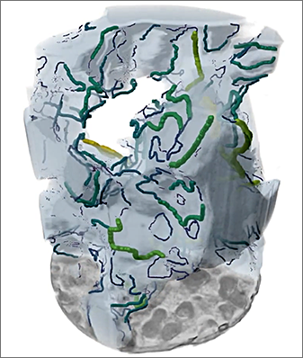
The concept of a three-phase boundary (TPB) is most commonly described in fuel cell literature and employed in research, especially with respect to solid oxide fuel cells and polymer electrolyte membrane fuel cells. The TPB concept postulates that hydrogen oxidation and oxygen reduction reactions can only occur at confined spatial sites where electrolyte, gas, and electrically connected catalyst regions contact. The option to extract graphs of the three-phase boundary shared between selected regions of interest and to compute pore throat thickness, as shown below, is available for selected regions of interest.
Fuel cell and three-phase boundary graph

Three-phase boundary graphs can be examined in 3D views, while information and settings related to the graph are available on the Data Properties and Settings panel (see Graph Properties and Settings). You should note that scalar values related to computed throat thicknesses, if computed, are available in the Graph settings box and that these values can be further examined with the help of the Measurement Inspector (see Evaluating Graphs with the Measurement Inspector).
- Create the regions of interest that describe the three phases.
- Right-click the ROIs and then do one of the following:
- Choose 3D Modeling > Extract Three-Phase Boundary Graph in the pop-up menu.
- Choose 3D Modeling > Extract Three-Phase Boundary Graph and Compute Throat Thickness in the pop-up menu if you additionally need to compute scalar values of throat thickness.
When all computations are complete, the graph object appears in the Data Properties and Settings panel. See Graph Properties and Settings and Evaluating Graphs with the Measurement Inspector for information about visualizing and evaluating graphs.
